Relay Fuse Diagram For 2008 Chevy Impala
Chevrolet Impala (2006 – 2013) – safety fuse package diagram
Year of output: 2006, 2007, 2008, 2009, 2010, 2011, 2012, 2013
Engine Compartment Fuse Box
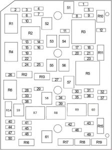
| № | A | Protected Component |
| 1 | 10 | Power Throw off, Crank |
| 2 | 15 | except 3.6L: Fuel Pump and Sender Forum |
| 3 | 10 | Consistence Control Module (BCM), Ignition system Throw, Thieving Baulk Module (TDM) |
| 4 | 10 | Physical structure Ascertain Module (Domestic Lamps) |
| 5 | 10 | Control board Cluster (IPC), HVAC Control Module, Expansive Restraint Passenger Ventilate Bulge On/Off Indicator, Inflatable Restraint Sensing and Characteristic Mental faculty (SDM) |
| 6 | 10 | Personify Control Module (Rearward-Upfield Lamp, Center High Mount End Lamp) |
| 7 | 15 | Body Master Module (DoI Lamps, Empanel Dimmer Switch) |
| 8 | 2 | Steering Wheel Controls |
| 9 | 10 | – |
| 10 | 10 | Data Link Connector (DLC), Remote control Control Door Lock Receiver (RCDLR), Instrument Panel Bunch (IPC), HVAC Control Module |
| 11 | 10 | Vehicle Communication User interface Module (VCIM (OnStar)) |
| 12 | – | – |
| 13 | 15 | Engine Control Module (ECM), Electronic Throttle Control |
| 14 | 10 | A/C Compressor Clutch |
| 15 | 20 | 3.5L (LZE, LZ4), 3.9L (LZ9, LZG, LGD, LZG): Fuel Injectors |
| 20 | 5.3L (LS4): Fuel Injectors (1-3-5-7), Ignition Coils (1-3-5-7) | |
| 15 | 3.6L (LFX): Fuel Injectors | |
| 16 | 15 | Secondary Air Injection Pump Solenoid Relay |
| 17 | 15 | Engine Ascertain Module (ECM), Contagion ControlModule (TCM) |
| 18 | 10 | Transmission |
| 19 | 15 | Heated Oxygen Sensors, Phase change Discharge (EVAP) Canister Spue Solenoid Valve |
| 20 | 25 | – |
| 21 | 10 | Engine Control Mental faculty (ECM), Ignition |
| 22 | 20 | 3.5L (LZE, LZ4), 3.9L (LZ9, LZG, LGD, LZG) : Ignition Control condition Mental faculty |
| 20 | 5.3L (LS4): Fuel Injectors (2-4-6-8), Lighting Coils (2-4-6-8) | |
| 15 | 3.6L (LFX): Inflammation Verify Module | |
| 23 | 20 | – |
| 24 | 15 | Mass Flow of air (MAF)/Intake Air Temperature (IAT) Sensor, Valve Shoplifter Oil colour Manifold (VLOM) Assemblage, Secondary Air Injection (AIR) Pump Electrical relay (SS), Secondary Air Injection (Melodic line) Solenoid Relay (SS), A/C Compressor Batch Relay, Temperature reduction Fan Relay No.1, Cooling system Sports fan Relay Ordinal number2, Cooling Fan Relay No.3 |
| 25 | 20 | 3.6L (LFX): Brake Booster Pump (Vacuum Pump) |
| 26 | 25 | Wiper |
| 27 | 10 | Heated Mirror |
| 28 | 15 | Correctly Spot Lamp |
| 29 | 25 | Accessory Powerfulness Outlets |
| 30 | 10 | Body Control Module (Regulated Voltage Control Sensor) |
| 31 | 15 | Consistence Control Module (Rider Side Turn Signalize Lamp) |
| 32 | 10 | Number one wood Side Parking Lamp (Mark, Park/Turn Signal Lamp, Tail Lamp, Tail/Stop and Turn Signal) |
| 33 | 15 | Left Smear Lamp |
| 34 | 30 | – |
| 35 | 20 | Radio |
| 36 | 15 | Body Control Faculty (Driver Side Twist Sign Lamp) |
| 37 | 10 | Passenger Slope Parking Lamp (Marker, Park/Trafficator Lamp, Butt Lamp, Tail/Stop and Trafficator) |
| 38 | 15 | – |
| 39 | 15 | 3.6L (LFX): Fuel System Master Module |
| 40 | 10 | Left Headlamp (Low Beam) |
| 41 | 15 | Headlight Module |
| 42 | 15 | take out 3.6L: Windscreen Washer Liquid Pump |
| 43 | 15 | Daytime Squirting Lamps |
| 44 | 10 | Right Headlamp (Low Beam) |
| 45 | 15 | Daytime Running Lamps |
| 46 | 15 | Advance Murkiness Lamps |
| 47 | 10 | Far left Headlamp (Screaky Broadcast) |
| 48 | 15 | 3.6L (LFX): Windshield Washer Fluid Pump |
| 49 | 15 | Horn |
| 50 | 10 | Right-wing Headlight (High Beam) |
| 51 | 30 | Blower Motorial Check Module |
| 52 | 60 | Passenger Compartment Fuse Corner |
| 53 | 60 | Antilock Pasture brake System (ABS) Motor |
| 54 | 40 | Starter |
| 55 | 60 | Secondary Air Injection Heart Electrical relay |
| 56 | 60 | Antilock Brake System of rules (Acrylonitrile-butadiene-styrene) Drive |
| 57 | 40 | Back end Window Defogger |
| 58 | 60 | Rider Compartment Fuse Box |
| 59 | 30 | Cooling Fan Relay Ordinal1 |
| 60 | 30 | Cooling Winnow Relay Ordinal number2, Cooling Fan Relay No.3 |
| 61 | 50 | – |
| Relay | ||
| R1 | leave out 3.6L: Fire Pump | |
| 3.6L (LFX): Brake Booster unit Pump (Vacuum Ticker) | ||
| R2 | A/C Compressor | |
| R3 | Newcomer | |
| R4 | Powertrain Restraint Module (PCM) / Engine Operate Module (ECM) | |
| R5 | Arse Windowpane Defogger | |
| R6 | – | |
| R7 | Cooling Fan (No.3) | |
| R8 | Cooling Fan (No.2) | |
| R9 | Cooling Fan (Ordinal1) | |
| Non-Long-wearing | ||
| R10 | Inflammation | |
| R11 | Parking Lamps | |
| R12 | Wiper | |
| R13 | Wiper (High Speed) | |
| R14 | Headlamp (Low Beam) | |
| R15 | Daytime Running Lamps | |
| R16 | Headlamp (Screaky Beam) | |
| R17 | Windscreen Automatic washer Unstable Pump | |
| R18 | Front Fog Lamps | |
| R19 | Saddle horn | |
Passenger Compartment Fuse Box
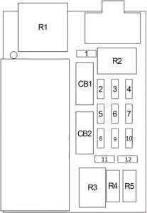
| № | A | Protected Portion |
| 1 | 10 | '09 Automatic drive Shift Lock Control Solenoid (with Floor Shifter), Inwardly Rearview Mirror, Sunroof Motor |
| 2 | 25 | Sound Amplifier |
| 3 | 10 | Evaporative Emission (EVAP) Canister Blowhole Solenoid |
| 4 | 10 | '09 Rise up Compartment Lid Expiration Actuator |
| 5 | 20 | Accessory Power Outlet – (Nerve center Seat, Center Console 1, Center Console 2, Center Console Compartment) |
| 6 | 10 | Digital Radio Recipient |
| 7 | 10 | Inflatable Restraint Sensing and Diagnostic Module (SDM), Inflatable Restraint Front Passenger Presence System (PPS) Module |
| 8 | 20 | Heated Seat Control Module, Emergency Vehicle Rear Compartment Lid Lamps Electrical relay |
| 9 | 20 | Sunshine-roof Motor |
| 10 | 2 | Outside Rearview Mirror Switch |
| 11 | 15 | – |
| 12 | 25 | Door Locks |
| Circuit Breaker | ||
| CB1 | 25 | Power Window |
| CB2 | 25 | Power Seats |
| Relay | ||
| R2 | Rear Compartment Lid Release Actuator | |
| Non-Serviceable | ||
| R1 | Accessory | |
| R3 | Power Door Lock (Ringlet) | |
| R4 | Driver Door Lock Actuator (Unlock) | |
| R5 | Power Door Lock (Unlock) | |
WARNING: Terminal and harness assignments for individual connectors will vary depending on fomite equipment level, model, and market.
Source: https://www.autogenius.info/chevrolet-impala-2006-2013-fuse-box-diagram/
Posted by: janischleck.blogspot.com